Tillery Hydroelectric Plant Oxygenation System, North Carolina
|
Tillery Dam and Lake
- The reservoir is located between Badin Lake and Blewett Falls Lake in the Uwharrie Lake region of NC
- Created by impounding the Pee Dee River
- Constructed in 1928, the dam is 86 feet tall, and 2800 feet long
- 4 Generating Units
- 84-MW
- 17,700 cfs total turbine capacity
- 5,000 cfs sumertime average daily flow
- 78 feet maximum depth
- Turbine venting system operational to maintain summer time tailwater DO levels
|
Tillery Oxygen Diffuser System
Objective
- Maintain 5mg/L daily average of dissolved oxygen in the hydropower releases
- Maintain instantaneous minimum of 4mg/L of dissolved oxygen in the hydropower releases
Facilities
- Two 15,000 gallon horizontal liquid oxygen tanks
- Ambient air vaporizers
- Fully remote operated flow control manifold
- Four diffuser lines, 3,500 feet long each
|
Four Diffusers
- 3,500 long
- 20 to 680 feet of underwater supply piping each
- 4 to 66 feet deep
The diffusers are positioned in the old riverbed along the east side of the forebay in front of the Hydroturbines and numbered 1 through 4 from the shoreline out, like the turbine units
In order to provide flexibility in the vertical placement of oxygen in the reservoir, the diffusers are insalled at two elevations
|
Depth finder plot of bubble plumes from 4 diffusers in operation. The outside diffusers (#1 and #4) are 14 feet off of the bottom; the inside diffusers (#2 and #3) are 2 feet off of the bottom
|
In the summer months, dissolved oxygen levels in the Tillery tailrace spike high in the morning due to photosynthesis of aquatic weeds, then drop to less than 3mg/L during hydro operations without the oxygen diffuser operating
|
|
Dissolved oxygen levels in Tillery tailrace are maintained above project goal of 5mg/L during hydro operations with the oxygen diffusers in operation
|
A cross section of the Tillery forebay without oxygenation exhibits a large volume of low DO water (August 8, 2011)
|
A cross section of the Tillery Forebay with oxygenation exhibits a large volume of water with enhanced DO levels (11:00am, August 10, 2011)
|
A three-dimensional representation of dissolved oxygen levels with the diffuser system in operation (August 12, 2011)
Turbine intakes are represented by vertical green rectangles, diffuser lines are represented by yellow and black lines
|
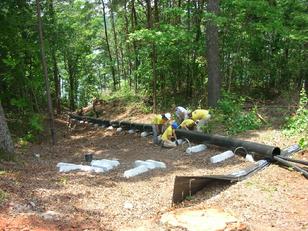 |
| The crew attaches weights to the sleeve pipe |
|
|
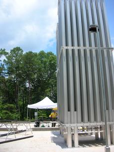 |
| The LOX site |
|
|
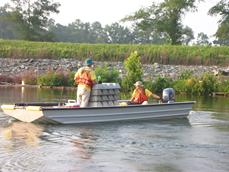 |
| Preparing to hang a boat load of weights |
|
|
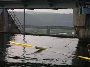 |
| Getting ready to pull a line out and sink it |
|
|
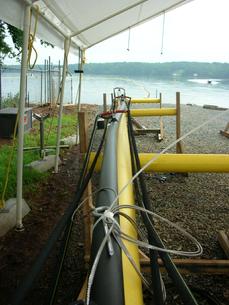 |
| Work site, Lake Tillery |
|
|
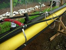 |
| Close-up of one of the diffuser lines being assembled |
|
|
|
|
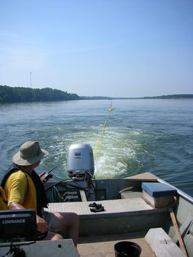 |
| Pulling a nice straight line! |
|
|
Publications and References
|
|
John U. Crutchfield, Jr., Mark Mobley, Richard J. Ruane, Paul Gantzer, Jon Knight, Paul J. Wolf
Awarded First Place, 2012 Technical Papers of the Year
in the category of Water Management and Movement
Presented at HydroVision 2012
Kentucky International Convention Center
July 17-20, 2012
Louisville, Kentucky
|
|