Lake Wallenpaupack Reservoir, Pennsylvania
|
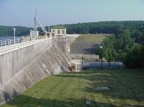
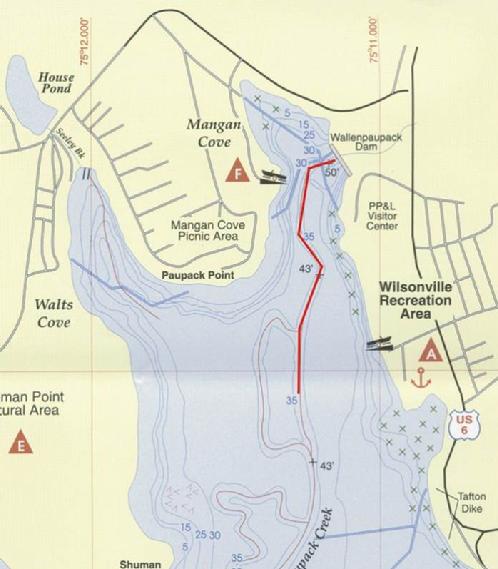
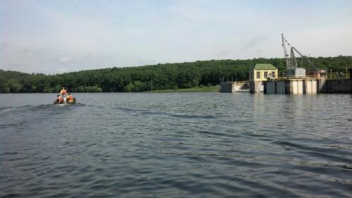
Lake Wallenpaupack and Wilsonville Dam
- Wallenpaupack Lake was formed in 1926
- 13 miles long, 5,700 acres,60 foot maximum depth
- One of the largest man-made lakes in PA, and a major center for tourism, boats, and recreation in the Poconos
- Wilsonville Dam is 1,275 feet long, 75 feet high
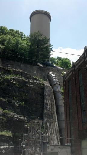
- The Wilsonville Powerhouse has 2 hydropower units, 22MW, 900cfs each
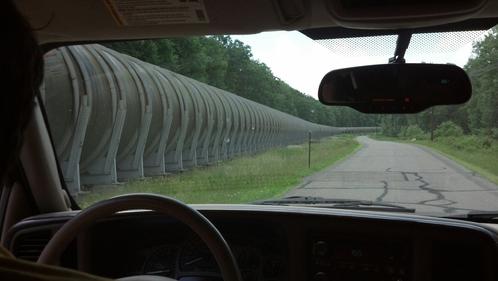
- 14 foot diameter penstock, 3.5 miles long, conveys water to the hydroelectric powerhouse
- 380 feet of head
- Water discharges into the Lackawaxen River
|
Lake Wallenpaupack Aeration System
Objective
- To reduce hydrogen sulfide odors
- Hypolimnetic aeration system
- Aerate one day's hydropower volume
- Extend > 2,200 feet upstream of dam
- Place oxygen low in hypolimnion
Facilities
- 50 HP air compressor, 100 scfm
- 3,000 feet of line diffuser in old river channel
|
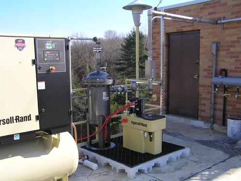 |
| The air compressor |
|
|
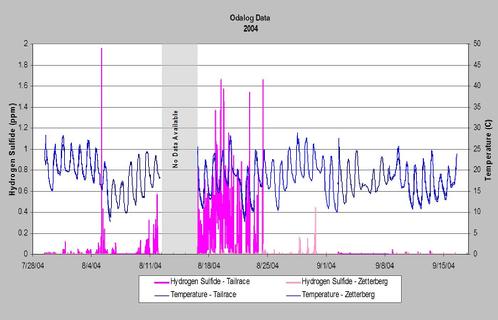
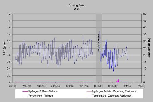
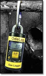
Tailrace H2S levels spiked to almost 2 parts per million in 2004 before aeration system installation. H2S levels at residences downstream of the powerhouse prompted numerous complaints.
Data and graphics courtesy of PPL and Kleinschmidt Associates
|
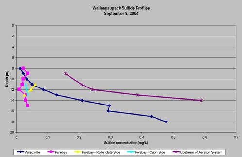
Sulfide levels in the reservoir are dramatically reduced in the forebay after just a few days of aeration system operation.
Data and graphics courtesy of PPL and Kleinschmidt Associates
|
H2S levels in the tailrace are maintained below 0.1 ppm with aeration system operation in 2005.
Data and graphics courtesty of PPL and Kleinschmidt Associates
|
 |
| H2S and ordors reduced immediately |
|
|
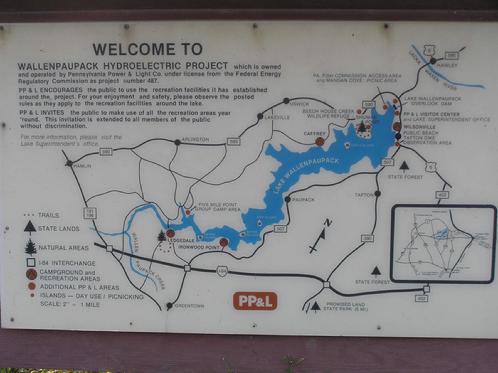 |
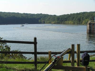
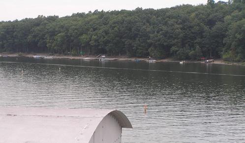
| Lake Wallenpaupack near Hawley, PA |
|
|
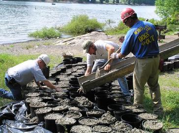 |
| Pouring the concrete weights |
|
|
|
 |
| Completed diffuser floating on reservoir |
|
|
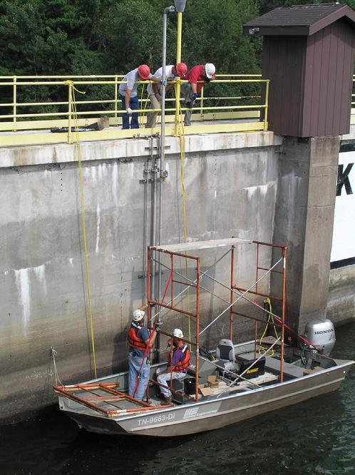 |
| Installing the stainless steel supply and buoyancy lines on the face of the dam |
|
|
 |
| The connection flanges for each line |
|
|
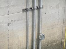 |
| SS unistrut holds up the lines |
|
|
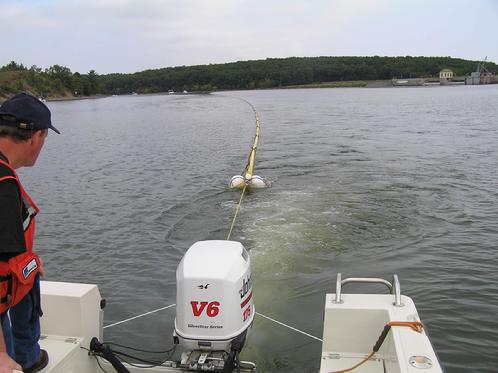 |
| Pulling the line diffuser into position |
|
|
 |
| The straight line bubble pattern after deployment |
|
|
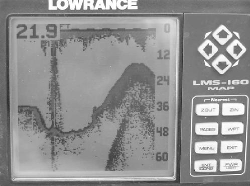 |
| Depth finder shows the bubbles from the diffuser floating to the surface |
|
|
|